Reissner-Mindlin / Naghdi shell
1. Kinematics
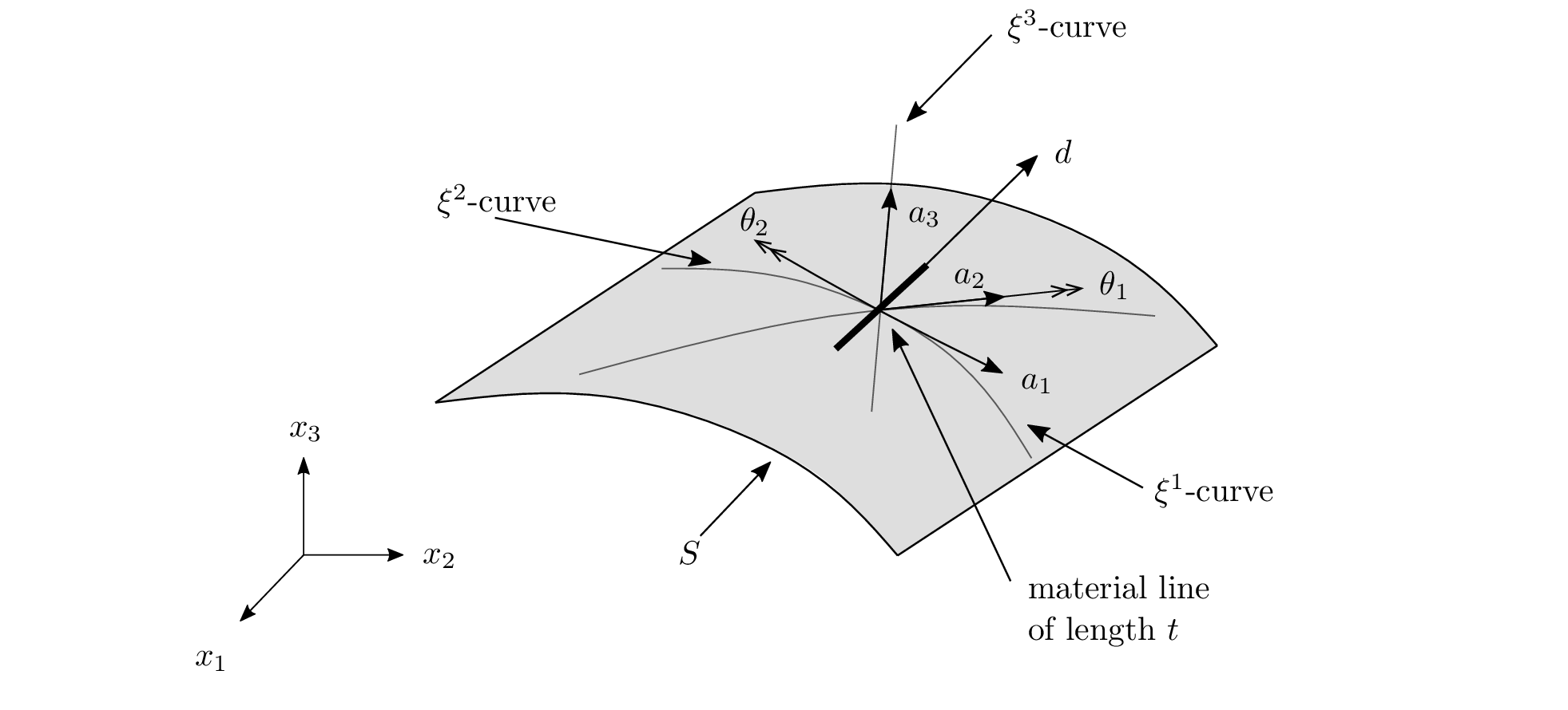
The Reissner-Mindlin kinematic relaxes the Kirchhoff-Love zero shear strain assumption through orthogonality of material lines. The shear strain measures the rotation of these material lines around the normal vector of the shell's midsurface $\hat{\mathbf{a}}_3$
\[\Phi(\xi^1,\xi^2,\xi^3) = \phi(\xi^1,\xi^2) + \xi^3\theta^\lambda(\xi^1,\xi^2) \mathbf{a}_\lambda(\xi^1,\xi^2) = \phi(\xi^1,\xi^2) + \xi^3\mathbf{d}(\xi^1,\xi^2)\]
where $\mathbf{d}(\xi^1,\xi^2)$ is the director at a point $(\xi^1,\xi^2)$ on the midsurface and $\gamma_\alpha=\mathbf{a}_\alpha\cdot\mathbf{d} - \mathbf{A}_\alpha\cdot\mathbf{G}_3$ is the transverse shear strain (the implemented Naghdi form uses the current basis $\mathbf{a}_\alpha$, with the reference value subtracted so $\gamma_\alpha=0$ in the undeformed configuration).
The surface basis vector are given by
\[\begin{split} \mathbf{g}_\alpha &= \frac{\partial \Phi(\xi^1,\xi^2)}{\partial \xi^\alpha} = \frac{\partial}{\partial\xi^\alpha}\left[\phi(\xi^1,\xi^2) + \xi^3\mathbf{d}(\xi^1,\xi^2)\right]\\ &= \mathbf{a}_\alpha + \xi^3 \mathbf{d}_{,\alpha} \\ \mathbf{g}_3 &= \frac{\partial}{\partial\xi^3}\left[\phi(\xi^1,\xi^2) + \xi^3\mathbf{d}(\xi^1,\xi^2)\right] = \mathbf{d} \end{split}\]
using the definition of $\mathbf{a}_\alpha$. From this, we can get the components of the metric tensor
\[\begin{split} g_{\alpha\beta} &= \mathbf{g}_\alpha \cdot \mathbf{g}_\beta = (\mathbf{a}_\alpha+\xi^3\mathbf{d}_{,\alpha})\cdot(\mathbf{a}_\beta+\xi^3\mathbf{d}_{,\beta})\\ &= a_{\alpha\beta} + \xi^3(\mathbf{a}_\alpha\cdot\mathbf{d}_{,\beta} + \mathbf{a}_\beta\cdot\mathbf{d}_{,\alpha}) + (\xi^3)^2\mathbf{d}_{,\alpha}\cdot\mathbf{d}_{,\beta}\\ &= a_{\alpha\beta} + \xi^3(\mathbf{a}_\alpha\cdot\mathbf{d}_{,\beta} + \mathbf{a}_\beta\cdot\mathbf{d}_{,\alpha}) + O(t^2) \\ g_{\alpha 3} &= g_{3\alpha} = (\mathbf{a}_\alpha+\xi^3\mathbf{d}_{,\alpha})\cdot\mathbf{d} = \mathbf{a}_\alpha\cdot\mathbf{d} + \xi^3\mathbf{d}_{,\alpha}\cdot\mathbf{d}\\ g_{33} &= 1. \end{split}\]
where the plane stress assumption gives $g_{33}=\mathbf{d}\cdot\mathbf{d}=1$ (unit director), and the shear components are non-zero. Two simplifications are applied:
In-plane metric $g_{\alpha\beta}$: the $(\xi^3)^2$ term is dropped (Love-Kirchhoff strain assumption, valid for $R_\text{min}>t/2$).
Shear metric $g_{\alpha3}$: the full expression is $\mathbf{a}_\alpha\cdot\mathbf{d} + \xi^3\mathbf{d}_{,\alpha}\cdot\mathbf{d}$. The second term vanishes for two consistent reasons. First, if $\Vert\mathbf{d}\Vert=1$ everywhere then differentiating $\mathbf{d}\cdot\mathbf{d}=1$ gives $\mathbf{d}_{,\alpha}\cdot\mathbf{d}=0$ exactly (the Rodrigues director satisfies this at nodes; the interpolated director deviates by $O(h^2)$). Second, even without a unit director, $\xi^3\in[-t/2,t/2]$ and $\mathbf{d}_{,\alpha}=O(1/R)$, so the term is $O(t/R)$ — the same order as the already-dropped $(\xi^3)^2$ correction, so consistency requires dropping it too.
The simplified metric is therefore
\[\begin{split} g_{\alpha\beta} &\approx a_{\alpha\beta} + \xi^3(\mathbf{a}_\alpha\cdot\mathbf{d}_{,\beta} + \mathbf{a}_\beta\cdot\mathbf{d}_{,\alpha})\\ g_{\alpha 3} &= g_{3\alpha} \approx \mathbf{a}_\alpha\cdot\mathbf{d}\\ g_{33} &= 1. \end{split}\]
The Green-Lagrange strain components follow from $e_{ij}=\tfrac{1}{2}(g_{ij}-G_{ij})$:
\[\begin{split} e_{\alpha\beta} &= \underbrace{\frac{1}{2}(a_{\alpha\beta} - A_{\alpha\beta})}_{\gamma_{\alpha\beta}} + \xi^3\underbrace{\frac{1}{2}(\mathbf{a}_\alpha\cdot\mathbf{d}_{,\beta} + \mathbf{a}_\beta\cdot\mathbf{d}_{,\alpha}) - B^0_{\alpha\beta}}_{\kappa_{\alpha\beta}}\\ e_{\alpha3} &= e_{3\alpha} = \frac{1}{2}(\mathbf{a}_\alpha\cdot\mathbf{d} - \mathbf{A}_\alpha\cdot\mathbf{G}_3) = \frac{1}{2}\gamma_\alpha\\ e_{33} &= 0. \end{split}\]
where $\gamma_{\alpha\beta}$ is the membrane (in-plane) strain, $\kappa_{\alpha\beta}$ the bending curvature change, and $\gamma_\alpha = \mathbf{a}_\alpha\cdot\mathbf{d} - \mathbf{A}_\alpha\cdot\mathbf{G}_3$ the transverse shear strain. In the reference configuration ($\mathbf{d}=\mathbf{G}_3$, $\mathbf{a}_\alpha=\mathbf{A}_\alpha$), all strains vanish identically.
$B^0_{\alpha\beta} = \tfrac{1}{2}(\mathbf{A}_\alpha\cdot\mathbf{d}^0_{,\beta} + \mathbf{A}_\beta\cdot\mathbf{d}^0_{,\alpha})$ is built from the interpolated initial director $\mathbf{d}^0 = \sum_I N_I \mathbf{G}_3^I$ — the same field the kernels rotate — not from the geometric patch curvature $B_{\alpha\beta} = \mathbf{A}_{\alpha,\beta}\cdot\mathbf{G}_3$. In the continuum the two coincide ($\mathbf{d}^0 = \mathbf{G}_3$); discretely they do not, and subtracting $B$ would leave a spurious reference bending strain $\kappa(0) = B^0 - B$ on curved or warped elements. That error does not converge away: with per-node frames (NodeFrames) the Scordelis-Lo roof stalls at 9.3% error under refinement, and with centroid frames the answer drifts past the reference rather than settling on it. With $B^0$ the reference configuration of every element is exactly bending-free, for the centroid frames and for NodeFrames alike.
Because $g_{\alpha3}$ is independent of $\xi^3$, the shear strain $e_{3\alpha}$ is constant through the thickness. This is the Reissner-Mindlin assumption: the director rotates rigidly, so shear does not vary. In 3D elasticity the shear stress is parabolic; the shear correction factor $\kappa_s=5/6$ compensates by matching the constant-strain energy to the parabolic-distribution energy of a rectangular cross-section. The Kirchhoff constraint $e_{3\alpha}=0$ is recovered in the limit $\mathbf{d}\to\hat{\mathbf{a}}_3$.
1.1 Director parametrization
There are a few ways to parametrize the the director vector, and the different choice lead to different discretization. One way is to discretize each of its components, leading to an additional 3 degrees of freedom per node. This is the simplest way, but requires enforcing $\Vert\mathbf{d}\Vert=1$ through a Lagrange multiplier approach and static condensation, which results in an overall complex implementation.
Another way is to use additive vector rotations starting from the midsurface normal
\[\mathbf{d} = \hat{\mathbf{a}}_3 + \theta_1\mathbf{T}_1 + \theta_2\mathbf{T}_2\]
which removes one unknown since we only require $\theta_1,\theta_2$ to fully describe $\mathbf{d}$. One issue with this formulation is that the unitary of the director is not enforced $\Vert\mathbf{d}\Vert\neq1$. This limits the formulation to small rotations $\Vert\mathbf{\theta}\Vert\ll1$ as large $\Vert\mathbf{d}\Vert$ would lead to large shear strains ($\gamma_\alpha=\mathbf{a}_\alpha\cdot\mathbf{d}$) resulting in shear locking as all the internal energy is taken by shear.
For finite rotation nonlinear shell, we would like to parametrize $\mathbf{d}$ in a way that naturally enforces the $\Vert\mathbf{d}\Vert=1$ constraint. One way to do this is through Rodrigue's parametrization
\[\mathbf{d} = \cos{\Vert\mathbf{\theta}\Vert}\cdot\hat{\mathbf{a}}_3 + \text{sinc}{\Vert\theta\Vert}\cdot(\theta_1\cdot\mathbf{T}_1 + \theta_2\cdot\mathbf{T}_2)\]
which guarantees $\Vert\mathbf{d}\Vert=1$ for any $\theta_1,\theta_2$ (since $\cos^2\Vert\theta\Vert + \Vert\theta\Vert^2\mathrm{sinc}^2\Vert\theta\Vert = 1$). The parametrization has a coordinate singularity at $\Vert\boldsymbol{\theta}\Vert=\pi$. In practice this is avoided by keeping each load increment small enough that $\Vert\boldsymbol{\theta}\Vert<\pi$ within a step, or by using a total-Lagrangian update that resets the reference configuration periodically. In the following, we will keep the director variation terms general since explicit variation of the director is messy, especially here since we use a Rodrigue's parametrization.
In practice, we use $\theta^2$ in the trigonometric functions to enforce directly the constraint on the rotations, but this means that for small rotations, we could take the square-root of a very small number, which could lead to overflow. To avoid this, we use a Taylor-series expansion to evaluate the trigonometric functions for $\mathbf{\theta}^2<10^{-6}$, and the normal expression otherwise.
2. Internal energy
The internal energy splits into membrane, bending, and transverse shear contributions
\[\mathcal{W}_\text{int} = \int_\omega \frac{1}{2}\left( N^{\alpha\beta} \gamma_{\alpha\beta} + M^{\alpha\beta} \kappa_{\alpha\beta} + Q^\alpha \gamma_\alpha \right) \sqrt{A}\,\mathrm{d}y\]
where the (thickness-integrated) stress resultants are
\[N^{\alpha\beta} = t\,\mathbb{C}^{\alpha\beta\gamma\delta}\gamma_{\gamma\delta}, \quad M^{\alpha\beta} = \frac{t^3}{12}\mathbb{C}^{\alpha\beta\gamma\delta}\kappa_{\gamma\delta}, \quad Q^\alpha = \kappa_s\, G\, t\, A^{\alpha\beta}\gamma_\beta,\]
with $\mathbb{C}^{\alpha\beta\gamma\delta}$ the (thickness-independent) contravariant plane-stress elasticity tensor, $G = E/(2(1+\nu))$ the shear modulus, and $\kappa_s = 5/6$ the shear correction factor. The membrane, bending, and shear resultants carry the through-thickness factors $t$, $t^3/12$, and $t$ respectively, and the transverse shear index is raised with the reference contravariant metric $A^{\alpha\beta} = (A_{\alpha\beta})^{-1}$. The strain measures are (using the Naghdi form with current base vectors $\mathbf{a}_\alpha$)
\[\gamma_{\alpha\beta} = \tfrac{1}{2}(a_{\alpha\beta} - A_{\alpha\beta}), \quad \kappa_{\alpha\beta} = \tfrac{1}{2}(\mathbf{a}_\alpha\cdot\mathbf{d}_{,\beta} + \mathbf{a}_\beta\cdot\mathbf{d}_{,\alpha}) - B^0_{\alpha\beta}, \quad \gamma_\alpha = \mathbf{a}_\alpha\cdot\mathbf{d} - \mathbf{A}_\alpha\cdot\mathbf{G}_3.\]
2.1 Residual and first variation
The residual is the first variation of $\mathcal{W}_\text{int}$. The membrane part is identical to the Kirchhoff-Love case ($\delta\mathcal{W}_\text{mem}=\int_\omega N^{\alpha\beta}\,\delta\mathbf{a}_\alpha\cdot\mathbf{a}_\beta\,\sqrt{A}\,\mathrm{d}y$, giving membrane_residuals_RM!); here we derive the bending and shear parts explicitly. Their first variation is
\[\delta\mathcal{W}_\text{bs}=\int_\omega \big(M^{\alpha\beta}\,\delta\kappa_{\alpha\beta} + Q^\alpha\,\delta\gamma_\alpha\big)\sqrt{A}\,\mathrm{d}y,\qquad M^{\alpha\beta}=D^{\alpha\beta\gamma\delta}\kappa_{\gamma\delta},\;\; Q^\alpha=\mathbb{C}_s^{\alpha\beta}\gamma_\beta,\;\; \mathbb{C}_s^{\alpha\beta}=\kappa_s G t\,A^{\alpha\beta}.\]
From $\kappa_{\alpha\beta}=\tfrac12(\mathbf{a}_\alpha\cdot\mathbf{d}_{,\beta}+\mathbf{a}_\beta\cdot\mathbf{d}_{,\alpha})-B_{\alpha\beta}$ and $\gamma_\alpha=\mathbf{a}_\alpha\cdot\mathbf{d}-\mathbf{A}_\alpha\cdot\mathbf{d}_0$ the strain variations are
\[\delta\kappa_{\alpha\beta}=\tfrac12\big(\delta\mathbf{a}_\alpha\cdot\mathbf{d}_{,\beta}+\mathbf{a}_\alpha\cdot\delta\mathbf{d}_{,\beta}+\delta\mathbf{a}_\beta\cdot\mathbf{d}_{,\alpha}+\mathbf{a}_\beta\cdot\delta\mathbf{d}_{,\alpha}\big),\qquad \delta\gamma_\alpha=\delta\mathbf{a}_\alpha\cdot\mathbf{d}+\mathbf{a}_\alpha\cdot\delta\mathbf{d}.\]
The displacement enters only through $\mathbf{a}_\alpha=\mathbf{A}_\alpha+\mathbf{u}_{,\alpha}$ (so $\delta\mathbf{a}_\alpha=\delta\mathbf{u}_{,\alpha}$ at fixed $\mathbf{d}$), the rotation only through the director (at fixed $\mathbf{a}_\alpha$). This splits the residual in two.
Displacement DOFs. Keeping the $\delta\mathbf{a}_\alpha$ terms and using $M^{\alpha\beta}=M^{\beta\alpha}$,
\[\delta\mathcal{W}^u=\int_\omega \delta\mathbf{a}_\alpha\cdot\underbrace{\big(M^{\alpha\beta}\mathbf{d}_{,\beta}+Q^\alpha\mathbf{d}\big)}_{\mathbf{P}^\alpha}\,\sqrt{A}\,\mathrm{d}y,\qquad \mathbf{r}_I^u=\int_\omega\big(\partial_1 N_I\,\mathbf{P}^1+\partial_2 N_I\,\mathbf{P}^2\big)\sqrt{A}\,\mathrm{d}y,\]
since $\delta\mathbf{a}_\alpha=\sum_I \partial_\alpha N_I\,\delta\mathbf{u}_I$. This is the $\mathbf{P}^\alpha$ of bending_residuals_RM! (to which the membrane $N^{\alpha\beta}\mathbf{a}_\beta$ traction is added).
Rotation DOFs. The director at node $I$ depends only on its own rotation $\boldsymbol{\varphi}_I$; with $\mathbf{d}=\sum_I N_I\mathbf{d}_I$ and $\mathbf{d}_{,\beta}=\sum_I \partial_\beta N_I\mathbf{d}_I$ the variations are $\delta\mathbf{d}=\sum_I N_I\,\mathrm{dd}_{Il}\,\delta\varphi_{Il}$ and $\delta\mathbf{d}_{,\beta}=\sum_I \partial_\beta N_I\,\mathrm{dd}_{Il}\,\delta\varphi_{Il}$, where $\mathrm{dd}_{Il}=\partial\mathbf{d}_I/\partial\varphi_{Il}$ is the Rodrigues director Jacobian. Keeping the $\delta\mathbf{d}$ terms,
\[\delta\mathcal{W}^\varphi=\int_\omega \big(M^{\alpha\beta}\mathbf{a}_\alpha\cdot\delta\mathbf{d}_{,\beta}+Q^\alpha\mathbf{a}_\alpha\cdot\delta\mathbf{d}\big)\sqrt{A}\,\mathrm{d}y,\]
and collecting the factor multiplying $\mathrm{dd}_{Il}$, with $\mathbf{S}^\alpha=M^{\alpha\beta}\mathbf{a}_\beta$,
\[r_{Il}^\varphi=\int_\omega \mathbf{F}_I\cdot\mathrm{dd}_{Il}\,\sqrt{A}\,\mathrm{d}y, \qquad \mathbf{F}_I = \partial_1 N_I\,\mathbf{S}^1 + \partial_2 N_I\,\mathbf{S}^2 + N_I\big(Q^1\mathbf{a}_1+Q^2\mathbf{a}_2\big).\]
The three parts of $\mathbf{F}_I$ are the bending moment acting through the tangent-plane rotation ($\mathbf{S}^\alpha$) and the shear acting through the director rotation ($Q^\alpha\mathbf{a}_\alpha$); both are contracted with the same Rodrigues Jacobian that maps $\delta\boldsymbol{\varphi}_I\mapsto\delta\mathbf{d}_I$.
In FerriteShells the explicit forms are implemented in membrane_residuals_RM! and bending_residuals_RM!. ForwardDiff-based residuals are also available as residuals_RM_FD! for both membrane, bending and shear contributions.
The advantage of the ForwardDiff-based residuals and tangents is that they are exact gradient and hessian of the internal energy, the explicit version should be as well but any small bug might break the energy consistency and lead to non-convergence of Newton-Raphson procedures. The explicit version is faster, but the ForwardDiff version is more robust, so it can be used as a reference to test the explicit version if you suspect an error in the explicit functions.
2.2 Consistent tangent and second variation
The tangent is the second variation. Linearising the residual, and noting again that $\mathbf{a}_\alpha$ is linear in $\mathbf{u}$ while $\mathbf{d}$ is nonlinear in $\boldsymbol{\varphi}$, gives material terms (from $\delta M^{\alpha\beta}=D^{\alpha\beta\gamma\delta}\delta\kappa_{\gamma\delta}$ and $\delta Q^\alpha=\mathbb{C}_s^{\alpha\beta}\delta\gamma_\beta$) and geometric terms (from the second variations $\delta^2\kappa,\delta^2\gamma$):
\[\delta(\delta\mathcal{W}_\text{bs})=\int_\omega \underbrace{\big(\delta M^{\alpha\beta}\delta\kappa_{\alpha\beta}+\delta Q^\alpha\delta\gamma_\alpha\big)}_{\text{material}}+\underbrace{\big(M^{\alpha\beta}\delta^2\kappa_{\alpha\beta}+Q^\alpha\delta^2\gamma_\alpha\big)}_{\text{geometric}}\;\sqrt{A}\,\mathrm{d}y.\]
Because $\kappa$ and $\gamma$ are each bilinear in $(\mathbf{a}_\alpha,\mathbf{d})$, the only non-zero second variations are the $\mathbf{u}$–$\boldsymbol{\varphi}$ cross terms and the $\boldsymbol{\varphi}$–$\boldsymbol{\varphi}$ term carried by $\delta^2\mathbf{d}$:
\[\delta^2\kappa_{\alpha\beta}=\tfrac12(\delta\mathbf{a}_\alpha\cdot\delta\mathbf{d}_{,\beta}+\delta\mathbf{a}_\beta\cdot\delta\mathbf{d}_{,\alpha})+\tfrac12(\mathbf{a}_\alpha\cdot\delta^2\mathbf{d}_{,\beta}+\mathbf{a}_\beta\cdot\delta^2\mathbf{d}_{,\alpha}),\qquad \delta^2\gamma_\alpha=\delta\mathbf{a}_\alpha\cdot\delta\mathbf{d}+\mathbf{a}_\alpha\cdot\delta^2\mathbf{d}.\]
This produces four blocks per node pair $(I,J)$.
uu block (3×3). Only $\delta\mathbf{a}_\alpha$ variations survive and there is no geometric part ($\delta^2\kappa,\delta^2\gamma$ vanish when both variations are displacements). The bending material term contracts the two curvature gradients and the shear material term the two $\delta\gamma$:
\[\mathbf{K}^{uu}_{IJ}=\partial_\alpha N_I\,\partial_\gamma N_J\,D^{\alpha\beta\gamma\delta}\,\mathbf{d}_{,\beta}\otimes\mathbf{d}_{,\delta}+\big(\partial_\alpha N_I\,\mathbb{C}_s^{\alpha\beta}\,\partial_\beta N_J\big)\,\mathbf{d}\otimes\mathbf{d}.\]
The first factor is the frame_stiffness(D, d₁, d₂) tensor $\mathbf{L}_{\alpha\gamma}=D^{\alpha\beta\gamma\delta}\mathbf{d}_{,\beta}\otimes\mathbf{d}_{,\delta}$.
uφ block (3×2). Column $l$ couples $\delta\mathbf{u}_I$ with $\delta\varphi_{Jl}$. Writing $c_\beta=\mathbf{a}_\beta\cdot\mathrm{dd}_{Jl}$ for the director rotation sensed by the current base vectors, the $J$-side increments are $\delta\kappa_{\gamma\delta}=\tfrac12(\partial_\gamma N_J c_\delta+\partial_\delta N_J c_\gamma)$ and $\delta\gamma_\beta=N_J c_\beta$, hence $\delta M^{\alpha\beta}=D^{\alpha\beta\gamma\delta}\delta\kappa_{\gamma\delta}$ and $\delta Q^\alpha=\mathbb{C}_s^{\alpha\beta}\delta\gamma_\beta$. The block sums a material and a geometric part:
\[\mathbf{K}^{u\varphi}_{IJl}=\underbrace{\partial_\alpha N_I\,\delta M^{\alpha\beta}\mathbf{d}_{,\beta}}_{\texttt{v\_bend}}+\underbrace{\big(\partial_\alpha N_I\,\delta Q^\alpha\big)N_J\,\mathbf{d}}_{\texttt{v\_shear}}+\underbrace{\big(g_{IJ}+q_I N_J\big)\mathrm{dd}_{Jl}}_{\texttt{v\_dir}},\]
with $g_{IJ}=\partial_\alpha N_I\,M^{\alpha\beta}\,\partial_\beta N_J$ (from $M^{\alpha\beta}\delta^2\kappa$) and $q_I=\partial_\alpha N_I\,Q^\alpha$ (from $Q^\alpha\delta^2\gamma$).
φu block (2×3). The transpose of the uφ block evaluated at $(J,I)$, guaranteed by the symmetry of $\mathcal{W}$; the code writes the same column into ke[col, 5I-4:5I-2].
φφ block (2×2). Both variations are rotations. The material part dots the $J$-side increments (assembled into $\delta\mathbf{F}_I=\partial_\alpha N_I\,\delta M^{\alpha\beta}\mathbf{a}_\beta+N_I N_J\,\delta Q^\alpha\mathbf{a}_\alpha$) with the $I$-side Jacobian $\mathrm{dd}_{Ik}$:
\[K^{\varphi\varphi,\text{mat}}_{Ik,Jl}=\delta\mathbf{F}_I\cdot\mathrm{dd}_{Ik}.\]
The geometric part is non-zero only on the diagonal $J=I$ (the director at $I$ depends on $\boldsymbol{\varphi}_I$ alone) and uses the Rodrigues Hessian $\partial^2\mathbf{d}_I/\partial\varphi_k\partial\varphi_l$:
\[K^{\varphi\varphi,\text{geo}}_{Ik,Il}=\mathbf{F}_I\cdot\frac{\partial^2\mathbf{d}_I}{\partial\varphi_k\,\partial\varphi_l},\]
with the same traction $\mathbf{F}_I$ as in the residual — the initial-stress (geometric) stiffness of the director.
The explicit implementation is in membrane_tangent_RM! and bending_tangent_RM!; ForwardDiff-based variants are available as tangent_RM_FD!. The FD tangent tests (rm_fd_tangent) check that the explicit blocks above reproduce ForwardDiff.hessian of energy_RM.
With a MITC shear treatment the shear strains $\gamma_\alpha$ are replaced by their tying-point interpolation, so the shear sensitivities $\partial\gamma_\alpha/\partial u$ in the uu/uφ/φφ blocks use the MITC B-operators (see bending_tangent_RM!) instead of the QP-direct $\partial_\alpha N\,\mathbf{d}$ and $N\,\mathbf{a}_\alpha\cdot\mathrm{dd}$ forms above. The bending ($\kappa$) terms are unchanged.